
French drains and house foundation footing drainage
by Bruno Di Lenardo, P. Eng.
PDF - French Drains and House Foundation Footing Drainage
PDF - Drains français et drainage des semelles de fondation d’une maison
Introduction
This paper is a summary that covers the drainage of conventional concrete foundations, as well as, permanent wood foundations (PWF). The PWF have a detailed CSA standard with very specific drainage requirements that go beyond that for conventional concrete foundations to ensure that ground water does not reach the level of the basement floor.
This paper summarizes the principles and details behind the National Building Code (NBC) provisions for the evacuation of groundwater that may accumulate around a house foundation. It should be noted that when we speak of groundwater, we are speaking of ‘surface water’ penetrating the soil from rain or from snow and ice during the spring thaw. This groundwater that is transient (passing through) which is slowly percolating down to the water table, where the soil is saturated throughout the year.
The Code provisions for a foundation drainage are intended to drain this temporary groundwater, originating from surface water, which may temporarily accumulate around the foundation walls, footings and basement floors. It does not cover the more complex design of a foundation where there is a constant water pressure on the foundation walls and basement floor, which should be avoided.
The figures shown below, for conventional concrete foundations, are extracts from the Illustrated User’s Guide – NBC 2010, Part 9 Housing and Small Buildings published in 2014. The figures shown addressing permanent wood foundations (PWF) are extracts from the publication, Permanent Wood Foundations, published by the Canadian Wood Council, published in 2016. For more information on these construction details, it is recommended that of these documents be obtained as they are essential for the more complete details of all the important aspects for house construction and permanent wood foundations.
Conventional Concrete Foundation - Drainage

Figure 1. Cross-section of French drain and gravel bed along concrete footing.
The strategy for drainage of conventional concrete foundations involves provisions for the installation layers of granular material (i.e. crushed-stone gravel) and drain pipes (often referred to as a French drain). The gravel size specified is intended to be open to water flowing through gravel and installed in a layer(s) to capture any groundwater and lead the water to the French drain. Typical drawings always show the following cross-section in Figure 1, where the French drain is surrounded by a gravel bed along the exterior side of the concrete footing. The gravel serves not only to capture and carry water but also to prevent soil from reaching and sealing the perforations in the French drain for the groundwater to enter the drain.

Figure 2. French drain and gravel bed with dimensions and sizes.
The Figure 2 below shows the installation in a 3-D drawing with details of the drain size and gravel size and depth of the gravel bed. The mention of the drain pipe or tile with the top-half covered with sheathing paper is historical. Today’s commonly used French drain is corrugated and ‘perforated’ plastic pipe. The perforated pipe is usually covered with a geotextile sock to prevent finer particles of soil from blocking the perforations.
Final Evacuation Point for Groundwater
What typical drawings don’t show, as in Figures 1 and 2, is where the water within the French drain needs to be brought to evacuate the groundwater away from the footings. The following Figure 3 mentions that the French drain is to be brought to a storm sewer, in urban/suburban areas, and to a ditch or dry well in rural areas that do not have a municipal sewer system. Also note the good practice shown to extend the downspout, from the roof gutter, as far away from the foundation wall as possible (~4ft.) to reduce the amount of surface water draining toward the footing. Similarly, connecting the downspout to drain to the French drain is not a good practice.
Figure 4 shows an even more complete picture of groundwater evacuation options. To evacuate the water around a footing the water within the French drain must be brought, by gravity, with a slope to a final evacuation location lower than the level of the footing. The French drain could be connected to: (i) a rigid plastic pipe to the final evacuation point or (ii) the perforated French drain and gravel bed could continue and slope towards the final evacuation point.

Figure 3. Perforated French drain to continue to a storm sewer, ditch or a dry well.
This lower level location could be a dry well being a large gravel bed buried in the ground designed to disperse the water. The rigid pipe or perforated French drain can also terminate at an open ditch as shown in Figure 4 for the sump pit groundwater. With both the dry well and the open ditch evacuation points, it is important to realize that during the spring when there is thawing and groundwater present, there is also a risk of overnight freezing which may build-up and block the drain. So some consideration must be given to the final location and risk of freezing which may need to be protected with rigid foam insulation.
Figure 4 also shows the installation of a sump pit with sump pump which is embedded within the gravel drainage layer beneath the basement floor. Any rising groundwater from below also needs to be pumped to a lower level final evacuation point. In some cases, to facilitate more rapid drainage to the sump pit, a French drain is installed circling the footing, on the interior side, and brought to the sump pit.
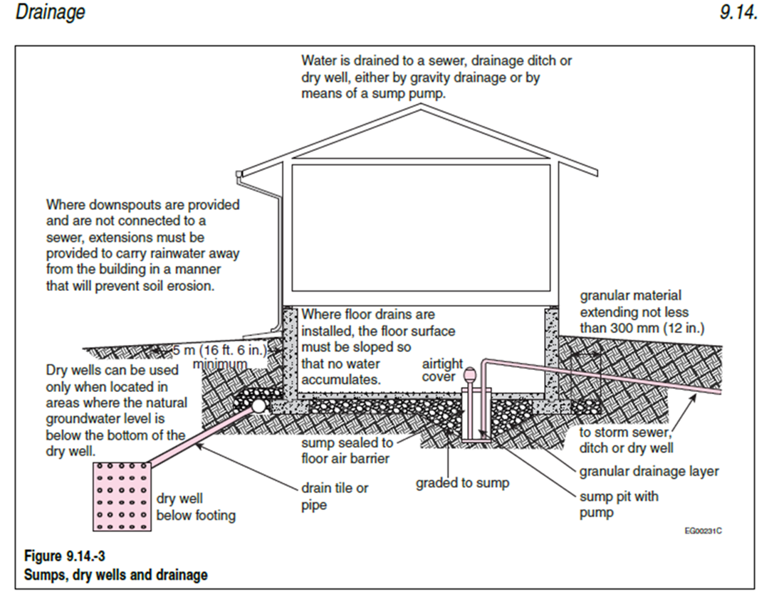
Figure 4. French drain and sump pit groundwater evacuated to locations away from the house.
The sump pump is an ‘active’ method for evacuating groundwater when there is too much groundwater that cannot be evacuated by the French drains. The French drains, along with gravel bed, sloped towards a dry well or open ditch is a ‘passive’ evacuation system that is always ready to perform its task. The sump pit is only activated when the passive evacuation system cannot keep up with the quantity of groundwater and it is rising too close to the basement floor. The sump pump is a back-up system that should always be considered in rural areas. It is also good practice to have the sump pit located close to a basement window in cases where there is a blockage of the buried drain pipe and the sump pump outflow pipe could be brought to the open window to evacuate the water at a distance as surface water.
Permanent Wood Foundations - Drainage
The construction of permanent wood foundations (PWF) is permitted within the National Building Code of Canada though the reference of the CSA S406-16 Standard, Permanent Wood Foundations for Housing and Small Buildings. The standard contains many pre-engineered details on the structural details in the construction of PWF but also highlights the importance of guaranteed positive drainage of the wood-based foundation system. In addition to this standard, the Canadian Wood Council (CWC) has published an excellent companion 2016 document entitles, Permanent Wood Foundations. The front page of this companion document is shown below.

Permanent Wood Foundations - Cover
Like the CSA S406 standard this CWC companion document provides more construction details but also expands on the importance of drainage of area around PWF foundation. To accomplish successful drainage of a PWF it begins with the selection of a proper site and the site preparation. Figure 5 below is an extract that shows areas to avoid and recommends higher ground with gentle slopes for better drainage.Figure 5. Site selection and site preparation for a PWF.
The PWF footings below the foundation walls may be preservative-treated wood or concrete footings. In both cases, it is the gravel bed below the entire basement and footing area that is designed to capture any groundwater and direct it to a designated sump pit. The specified gravel size is larger than that specified in the NBC conventional concrete foundations and would allow for more water flow. Figure 6 below shows the prescribed wall construction and gravel throughout leading to the sump pit. The sump pit having a sloped drain pipe to be brought to the final evacuation location be it a dry well or roadway ditch where water drainage away from the house foundation is certain. Note that a perforated French drain is not permitted with PWF as the gravel bed is load bearing to support the footings and should not have a pipe within the gravel bed.

Figure 5. Site selection and site preparation for a PWF.
Like the CSA S406 standard this CWC companion document provides more construction details but also expands on the importance of drainage of area around PWF foundation. To accomplish successful drainage of a PWF it begins with the selection of a proper site and the site preparation. Figure 5 below is an extract that shows areas to avoid and recommends higher ground with gentle slopes for better drainage.
The PWF footings below the foundation walls may be preservative-treated wood or concrete footings. In both cases, it is the gravel bed below the entire basement and footing area that is designed to capture any groundwater and direct it to a designated sump pit. The specified gravel size is larger than that specified in the NBC conventional concrete foundations and would allow for more water flow. Figure 6 below shows the prescribed wall construction and gravel throughout leading to the sump pit. The sump pit having a sloped drain pipe to be brought to the final evacuation location be it a dry well or roadway ditch where water drainage away from the house foundation is certain. Note that a perforated French drain is not permitted with PWF as the gravel bed is load bearing to support the footings and should not have a pipe within the gravel bed.
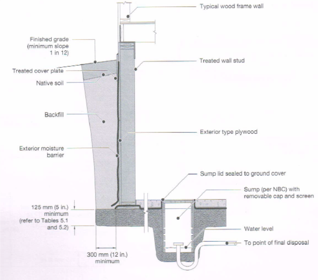
Figure 6. Gravel bed over entire basement and footing areas draining into sump pit.
Figure 7 below shows a top view of the gravel bed, extending a minimum of 300mm (12 inches) beyond the foundation footing, and leading to a centralized sump pit. The excavation for the gravel bed should also be sloped towards the planed sump pit location to provide positive drainage to the sump pit. The Figure also shows the sump pit could be in the same trench as other underground services such as water line and also shows the possible need for the pipe for soil gas extraction.
In the case where concrete footings are being used, it is important that the gravel bed continue to be interconnected. So the gravel that is 300mm (12”) or more beyond the footing must be connected to the gravel bed below the basement floor to carry groundwater to the sump pit. Figure 8 below shows that when concrete footings are used, one solution is to install 60mm (2 1/4 in.) plastic pipes within the concrete footings every 1.2m (4 feet) to allow for the passage of groundwater from the gravel bed on the exterior side of foundation wall to the gravel bed on the interior side.
Conclusion

Figure 7. Top view of gravel bed and central sump pit location.
The above diagrams are intended to emphasize the importance of planning for the drainage and the evacuation of groundwater or foundation systems to perform as expected. For conventional concrete foundations, a gravel bed on the exterior of a foundation wall with perforated French drain connected to dry well or roadway ditch, are expected to work together to drain groundwater away from the exterior of the foundation. While a sump pit with pump below the basement level, are expected to evacuate water from the below the basement level to a designated evacuation point. For PWF foundations, it is the extensive gravel bed, not broken up by footings, to carry groundwater to the centralized sump pit having a drain sloped to a designated evacuation point.
For more detailed information on drainage solutions and construction details it is recommended that the Illustrated Code of the NBC be consulted, as well as, for PWF the latest edition of the CSA S406 standard and the CWC companion document for PWF foundations.

Figure 8. Concrete footings with pipes at 1.2m (4 feet) on center to allow passage of water.
Part of the Eagle's Eye on Housing series - read more